MDD PSU Test
All troubleshooting assumes a PMU reset has failed return to startup, and assumes that all third party external devices and PCI cards are removed/disconnected.
Of course, a known good power cord is also assumed
to be in use.

You will need a volt meter to test the PSU.
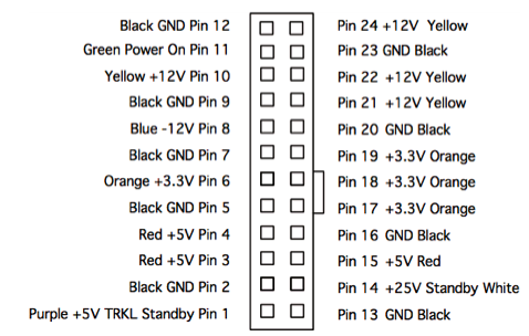
Use the PinOut (top of this page) to ID the pins.
To test the PSU, start with these steps:
1. Plug in the computer, but don't turn it on. The 24 pin connector needs to stay connected to the logic board.
2. Connect the black lead of the volt meter to pin 12 of the 24 pin connector, and connect the red lead of the meter to pin 14.
The meter should measure +25V (±1v).
If +25V isn't read, recheck the volt meter connections and try again.
If +25V is not present, replace the PSU.
If +25V on pin 14, go to the next step.
3. Check the trickle voltage by connecting the black lead to pin 12 of the 24 pin connector, and the red lead of the volt meter to pin 1.
The meter should measure about +5V.
If +5V isn't measured, recheck and measure the voltage again. If +5V is still not present, replace the PSU.
If after the completion of step 3, pressing the power button has no effect, and the PSU fans do not move, the PSU is likely bad.
4. Connect the black lead to pin 12 of the power supply connector;
connect the red lead to pin 24.
The volt meter should measure approximately +12V.
If you do not get a reading of +12V, recheck connections and measure again. If voltage is still not present, replace the PSU.
5. Connect the black lead to pin 12 of the power supply connector;
connect the red lead to pin 6.
The volt meter should measure approximately +3.3V.
If you do not get a reading of +3.3V, recheck connections and measure again. If voltage is still not present, replace the PSU.
6. Connect the black lead to pin 12 of the power supply connector;
connect the red lead to pin 3.
The volt meter should measure approximately +5V.
If you do not get a reading of +5V, recheck connections and measure again. If voltage is still not present, replace the PSU.
7. Connect the black lead to pin 12 of the power supply connector;
connect the red lead to pin 10.
The volt meter should measure approximately +12V.
If you do not get a reading of +12V, recheck and measure again. If voltage is still not present, replace the PSU.
If after these tests, all voltages are as they should be, the PSU is probably fine.
Another common area of failure would be the power button board.
Replacing the power button board with a known working unit is recommended.
For the No Glow Machine....
All G4 Mirror Drive Door models
Sunday, June 7, 2009